Title : Chapter 5 : Modeling Process

|
Location : Home > Methods > Simulation > System Dynamics > Introduction to System Dynamics Title : Chapter 5 : Modeling Process |
 |
Modeling Process

There is more to modeling than just being able to build a model on a computer. Ultimately the goal of building a system dynamics model is to improve the way that people understand systems and improve their decision making. In this chapter, we share some thoughts and ideas about the process of creating system dynamics models and how these models can be used to test options through computer simulation "experiments."
The Modeling Process
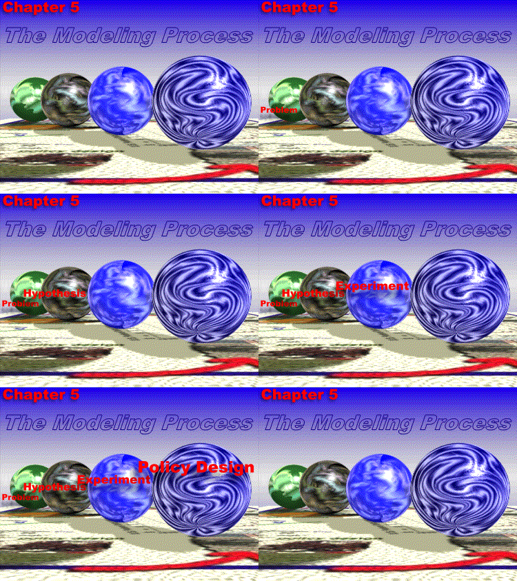
The goal of any modeling effort is to understand and explain the behavior of a complex system over time. As we discussed in the previous chapters, knowing a system's patterns of behavior speaks volumes about its structure. For a decision maker, understanding the structure of a system is a critical first step in designing and implementing effective policy. There are two ways in which a system dynamics model can aid in understanding complex problems. A completed model can be used to test alternative policy options (i.e. conduct experiments). However, it should be noted that there is great benefit to participating in the model building process itself. Practitioners have found that long-term learning tends to come from the model building process, so it is important to involve the decision maker from the beginning. With this in mind, we can think of the modeling process as having the following steps:
Identify "SD" Problem
One of the early lessons learned in building system dynamics models is the importance of modeling a problem rather than an entire system. Focusing on a particular problem provides a boundary to the modeling process and forces the modeler to consider only system variables that relate specifically to the problem in question. Although your understanding of the real problem might change as the process unfolds, it is still critical to begin with a focused problem statement.
Develop Hypothesis (mapping mental models)
With a clearly defined problem statement in hand, the first model building step is to develop a theory of why the system is behaving the way that it is. Tools such as causal loop diagrams and stock and flow networks can be used to map out a set of assumptions about what is causing the "reference modes" of the system to behave a particular way. Although the actual process of developing this theory (causal diagram) varies from person to person, we summarize the basic steps (See box below) in the process as a general guide.
|
This is an important stage to collect information about the problem through brainstorming with groups, data, literature, and of course, personal experience.
Test Hypothesis (challenging mental models)
Once you have developed a pen and paper theory about the system it is time to develop a computer model of your theory to see if it will re-create the behavior over time seen in the reference modes. The mathematical representation requires a deal of precision around the relationships between different elements in the system. Being forced to shape a consistent mathematical model of a system often challenges and evolves our own mental model assumptions of how we thought it worked. Before each simulation run of the model, think through how you expect the model to behave. If it behaves differently, it either means something is wrong in the model or you have just discovered an opportunity to challenge your mental model!
Test Policies (improving mental models)
With a basic model that seems to be able to explain why the problem is behaving the way that it is, you can look for policy interventions that lead to more desirable long term system behaviors. A good way to start this process is to first identify the key decisions (critical decisions/policies that the organization makes), indicators (what you need to see from the system to assess the decision), and uncertainties (most fragile assumptions about the relationships or outside world) associated with the problem. Then try out different possible sets of decisions under different assumptions about the uncertainties. Look for tradeoffs between short term behavior and long term behavior.
Management Flight Simulators
Through the process of developing a system dynamics model, the modeler has created a complex map of interrelationships and a better understanding of how the system will behave over time under different policy scenarios. One of the great challenges of developing models is in trying to communicate the insights gained to people who did not develop the model. Presenting a report to a manager of all the things he or she should do differently from what someone else has learned in a model works only if the conclusions of the model were what they were planning to do in the first place. But a model can provide more than just bullet point conclusions, it can also be used to create a simulated "practice field" where these managers and other people can try managing the system by making decisions themselves. We call these simulated worlds management flight simulators. Through these simulators they can learn about the model of the system and improve their own assumptions about the short and long term effects of different decisions. In a management flight simulator, users of the model are placed in the position of managing the system. Each year (or month, or quarter) they must make decisions to try to meet some goal in the system. To help with this, a snazzy interface is typically run "on top of" the system dynamics model that makes the information more accessible. Generally, there are four kinds of information presented:
[Management Flight Simulation Example]
The Product Development Flight Simulator was developed by Daniel Kim and Don Seville at the Organization Learning Center at MIT to teach users the dynamics and highly complex nature of the product development cycle. The user had three primary objectives or requirements:
For this simulator, the product development project was separated into two categories of tasks: product engineering tasks (100 total tasks to complete), and process engineering tasks (100 total tasks to complete). Each category represented a stock of work (tasks) that would be drawn down at a particular work rate. The product engineers (PE) were responsible for product design and testing. Process engineers (PcE) were responsible for designing and building the manufacturing process to turn the design into a marketable product.
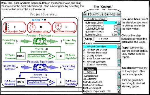
Figure 1 shows the basic layout of the product development flight simulator. During the simulation, each stock of work was gradually drawn down as the engineers worked. Regardless of whether all the engineering design and process work was completed, the product was manufactured and released into the market on the scheduled day. If the all or a majority of the work was completed, the quality of the product was high. However, if a significant amount of tasks remained, then the quality of the product was low on the day of release. Product sales depended heavily on whether the product was released by the target release date and was of a competitive quality.

Figure 1: Basic Layout of the Product Development Flight Simulator
As the "pilot" of this simulator, each week of the simulation the user was expected to decide how many engineers to hire or layoff, the number of work hours in a week, the scheduled completion date for each team, the amount of time spent coordinating between the two teams, and the quality "target" for the product. The choice for each of the system variables influences the rate at which the engineers accomplish their work, the resulting quality level, and the rate of engineer attrition due to stress and fatigue. In this case, the flight simulator served as a laboratory in which a wide variety of different management strategies could be tested. More importantly, the consequences of various strategies could be explored systematically without risking "trial and error" learning on the real firm!
Just for fun
In the box below, we provide you an opportunity to try out a sample simulator yourself. After reading the brief introduction to our Rocket Simulator, feel free to run the simulator by clicking on the animated figure.

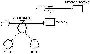
Rocket Simulator is a simple system dynamics model that simulates the motion of a rocket being launched from a planet's surface. We used a system dynamics stock and flow structure to describe a body in motion such as a rocket or an automobile in terms of its mass, acceleration, velocity, distance traveled, and the forces acting on it. The figure on the right shows the basic structure of the rocket simulation model. As the pilot, you control two of the simulation model's parameters: the throttle and direction. The THROTTLE controls the rocket's thrust and fuel burn rate. The ROCKET ANGLE controls what direction the rocket is pointing. This simulation uses simple equations of motion to teach concepts of accumulation and system delay as well as demonstrate how even simple systems can behave in a complex and non-intuitive way. |
[Previous] |
|
[Next] |
 |
Updated : 2005/07/23 |